Void I2C_Repeated_Start() : sends a repeated start signal. Void I2C_Start() : this function sends a start signal to the I2C slave device. Void I2C_Init(uint32_t i2c_clk_freq) : initializes the MSSP module in I2C mode (master mode) with a clock frequency of i2c_clk_freq. For that I wrote some functions which allowed me to communicate with the RTC chip using the MSSP module: The PIC16F887 has one MSSP module which can work in I2C mode. The MPLAB XC8 compiler doesn’t have any I2C library for the PIC16F887 microcontroller which means we’ve to write own I2C function codes. To be able to compile the C code, a small LCD library for MPLAB XC8 compiler is required which can be downloaded from the following link:Īfter the download, add the library file ( LCD_Lib.c) to project folder.
#Real time clock ds1307 library code#
The C code below is for MPLAB XC8 compiler, it was tested with version 2.00 installed on MPLAB X IDE version 5.05. Interfacing DS1307/DS3231 RTC with PIC microcontroller C code: In this project the PIC16F887 microcontroller runs with its internal oscillator 8 MHz, MCLR pin is configured as an input pin. A (anode) and K (cathode) are the back light LED pins.

VEE pin is used to control the contrast of the LCD.

VDD to +5V and A to +5V through 330 ohm resistor VEE to the variable resistor (or potentiometer) output pin VSS, RW, D0, D1, D2, D3 and K are connected to circuit GND (ground) The 16×2 LCD screen is connected to the PIC16F887 microcontroller as follows: The two push buttons in the circuit are used to set time and date of the real time clock, button 1 (B1) is connected to RB0 pin (#33) and button 2 (B2) is connected to RB1 pin (#34) of the PIC16F887 MCU. (All grounded terminals are connected together) The following image shows circuit connection of PIC16F887 MCU, DS1307 RTC and 16×2 LCD screen.Īnd the below image shows the same circuit but with DS3231 board instead of DS1307:

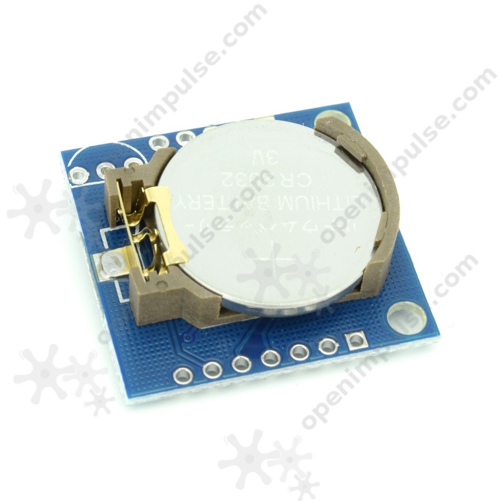
Interfacing DS1307/DS3231 RTC with PIC microcontroller circuit: Generally the DS1307 or DS3231 board contains the main chip (DS1307 or DS3231 IC), 2 pull-ups resistors and battery holder. 10k ohm variable resistor or potentiometer.The components required for this project are listed below. Interfacing LCD with PIC microcontroller | MPLAB Projects The compiler used in this project is Microchip MPLAB XC8 (MPLAB X IDE with MPLAB XC8 compiler). Time and date are displayed on 16×2 LCD screen and they can be set with two push buttons connected to the MCU.
#Real time clock ds1307 library how to#
This post shows how to build a simple real time clock using PIC16F887 microcontroller and DS1307 (or DS3231) RTC chip.


 0 kommentar(er)
